 2025/11/21
Background knowledge
With the rapid development of consumer electronics, electronic devices are trending toward being "smaller, lighter, and thinner," a shift that drives continuous advancements in circuit board and connector technologies. Differential measurement technology not only serves as the quality "gatekeeper" for circuit board connectors but also forms the core foundation for achieving precision in electronic manufacturing.
In the early stages of the circuit board connector manufacturing industry, companies primarily used contact-based measuring tools like micrometers and dial indicators for segment difference detection due to lower precision requirements. These manual methods proved inefficient and inadequate for modern production line batch testing needs. As connector precision standards increased.
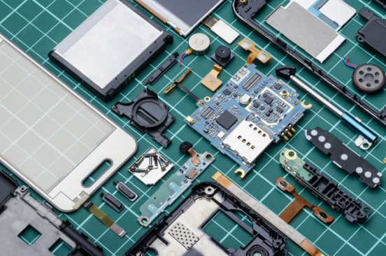
the limitations of traditional contact-based measurement became increasingly apparent. Against this backdrop, 3D industrial cameras emerged as the key technological solution, achieving precision breakthroughs from millimeter-level to nanometer-level accuracy to overcome these detection challenges.
Camera Selection
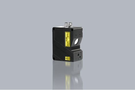
Today, we're excited to showcase the LVM3430 line laser 3D camera, a new addition to Next Vision Tech's LVM3400 series, and its real-world applications in the consumer electronics industry!
The LVM3430 3D smart sensor features a full-frame 2000Hz acquisition rate, with ROI settings supporting up to 30000Hz. It effortlessly handles high-speed dynamic scenes, delivering repeatable precision of 1.6μm and capturing every detail, making it ideal for high-precision industrial inspection.
surveillance project
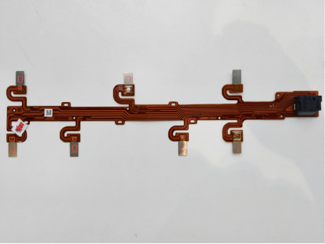
Measure the connection segment difference. The measurement area is shown in the red box below.
·Product dimensions: 250mm x 90mm
Complete the test in 4 seconds
*Product image
Check the environment and installation method.
·Scanning method: The camera is fixed, and the test sample is scanned along a central straight line.
·Triggering method: Encoders trigger to output stable AB phase difference signals
·Communication mode: TCP/IP Ethernet
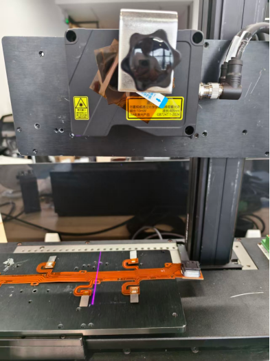
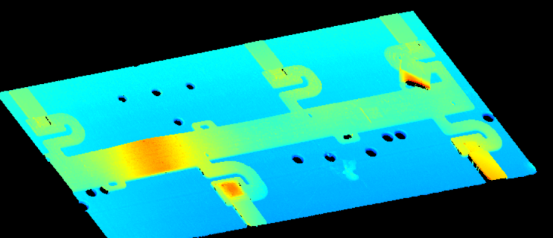
Image capture effect
measured data
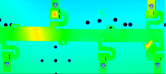
*Figure 1 shows the baseline area
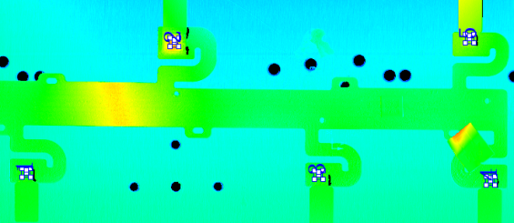
Figure 2 shows the measurement area.
·Based on the depth image captured by the camera, the product is initially positioned
· Obtain five reference areas as shown in Figure 1
· Obtain five measurement areas as shown in Figure 2
·Calculate the segment difference data separately
DA
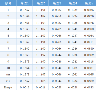
*10 static measurements, with a tolerance of 0.01mm or less

